3 Watt LED Bike Light
Experiments
May, 2008, Rev
d.2
Michael Krabach
Contents
Prototype 10 – Red Rear Multi-mode Flasher with Wide Optics
This
prototype is an attempt to use a bright 3 watt red LED in a flashing
mode to project a wide rear warning flasher. From the previous
prototypes I had extra L2
Optics OPTX and wide beam diffusers. I had also accumulated
various regulator/controller circuits. My desire was to have a
multi-mode controller that would hold the last setting. I found that
very few cheap controllers have this feature. I started with the KAI
SKU-3151 regulator which has 17 modes, grouped in three groups.
The specs say 19 modes, but I find only 17.
The modes and groups
follow.
(Directions to
configure modes and groups.)
(1) Low, Med, High, Fast strobe,
SOS
(2) Low, Med, High
(3) Low, Med, High, Fast strobe, Police
strobe, Med strobe, Slow strobe, Beacon strobe, SOS
This batch
of circuit boards had quality control problems and out of 5, I only
got one that worked properly. (Similar controllers are the DX
SKU-7882 which are slightly different are discussed in prototype 12.)
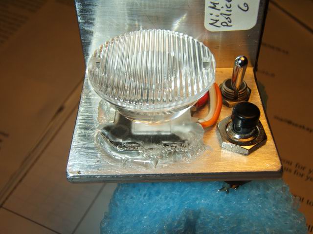
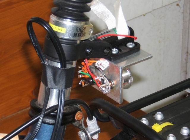
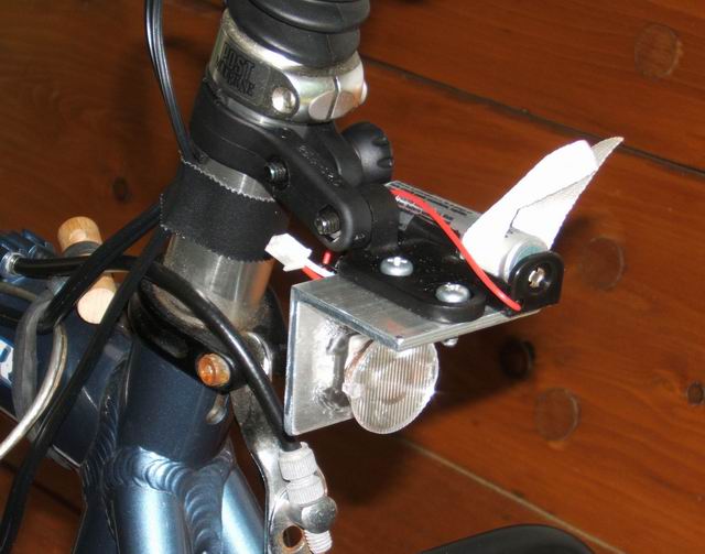
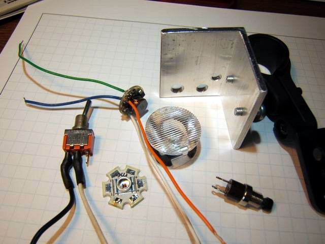
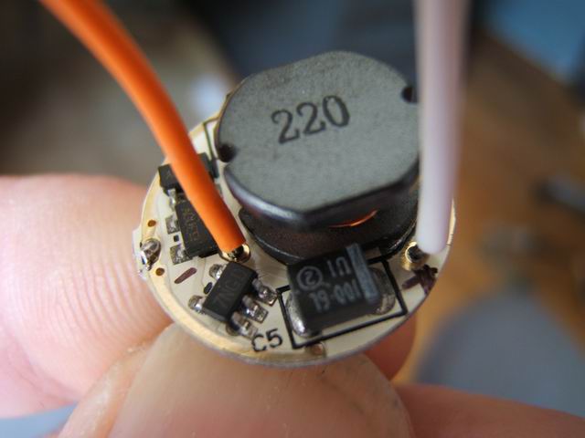
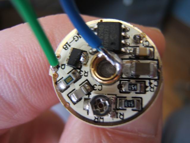
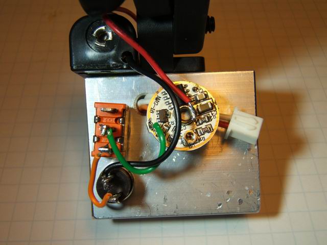
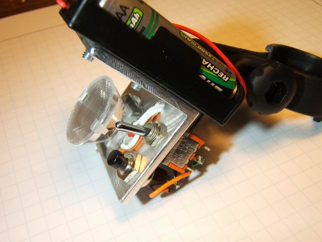
Mounting the LED star and switches in a sealed unit was a problem, so I ended up using the standard 1 1/4” aluminum angle stock and attached a surplus reflector mount on the top for attaching to the bike seat stem. Since the modes are changed by clicking the power switch, I used two switches. A toggle for the main switch and a make/break push switch in-line for changing the controller modes and groups. The red LED (DX SKU-1776) appears to be a 3 watt and has a vf of 1.9~2.2v. This means that most regulators which are set up for a vf of 3.7v would over drive the LED. The KAI SKU-3151 regulator in the third photo shows the white (+) and orange (-) leads that power the LED. The fourth photo shows the blue (+) and green (-) input leads. The input voltage is adjustable via a trimpot from 0.8 to 7 volts. I used the trimpot to reduce the output voltage to the lowest possible value which was 1.4v with a single AA battery for the low brightness. The trimpot is seen at the bottom of the fourth photo above. I added a connection point (white mini connector in first photo below) to monitor the voltage to the LED as I adjusted the pot. Subsequently I found it convenient to turn the pot while observing the brightness of the LED, making it as dim as possible. The pot is 360 deg with no stops, so it is easy to observe the hi/lo transition point. I bonded the star LED to the angle stock with Arctic Silver Thermal Adhesive. The final prototype is seen below.
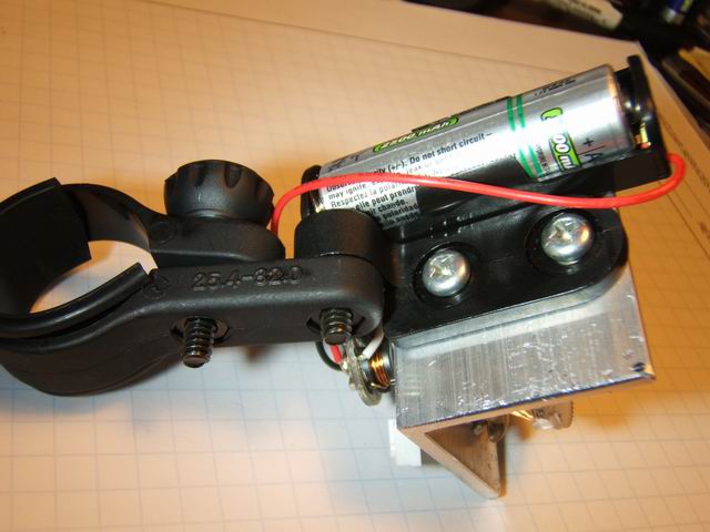
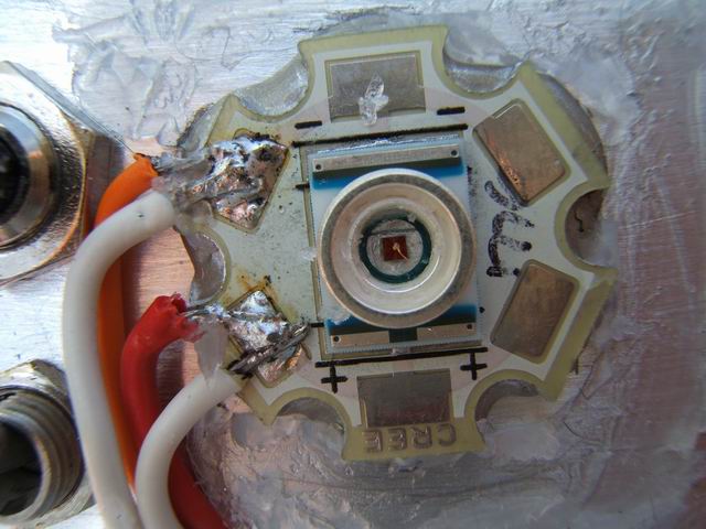
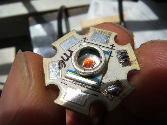
After assembling the prototype I found that it was not working properly, specifically after I used GE Silicone II sealant to bond the L2 optics to the LED star. When I cut away and removed the sealant, I found that the plastic lens on top of the LED emitter was loose. Evidently some of the sealant around the LED power leads got into the central area. Somehow the sealant on the LED lens was dissolved. The bare damaged LED is seen in the first photo below. I used a gentle blowtorch on the back of the aluminum angle stock, behind the LED to remove the star LED. The Arctic Silver Thermal Adhesive melts enough to allow the removal of the star plate. After installing another LED I used a urethane based glue to attach the L2 optics to the LED star. I was careful not to get any glue under the optics between the power leads. Of course removing the LED in the future will be much more difficult having used the urethane glue. The regulator is attached to the back of the prototype with rubber contact cement, as is the Radio Shack battery holder on the top of the angle stock, as seen in the third and fourth photos below. This unit draws 53, 360, 880 ma for Lo, Med, Hi modes. On police strobe, which uses the Hi level, it will last for about 6 hours with NiMH batteries.