3 Watt LED Bike Light
Experiments
February,
2008, Rev c
Michael Krabach
Contents
Prototype 4 - Single Cree and regulator
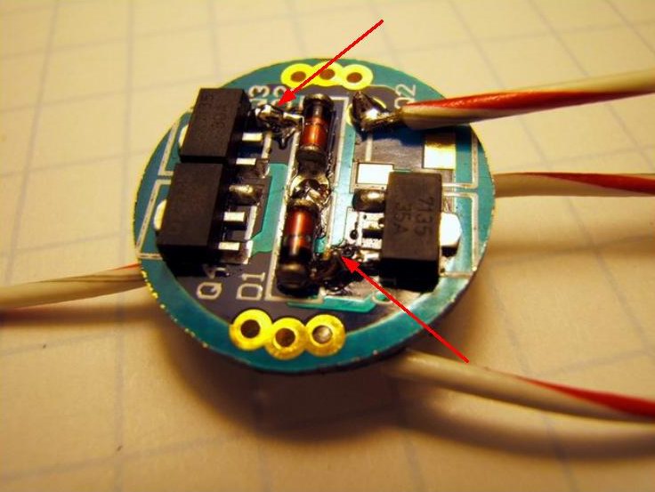
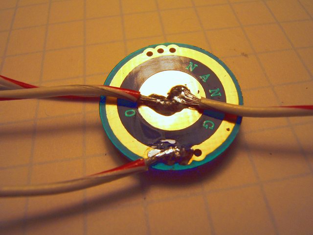
To further reduce the cost of the bike light, this prototype uses only one Cree 3 Watt LED. The idea being that for casual riding on a bike path or quiet streets a single LED should be enough. This light uses a brighter Cree LED than the other models. It uses a bin Q5 vs the P4. (I had ordered a Q5 just to see the difference.) To make sure it had enough light the current regulator was a DX SKU-1885 which provides 1000 ma for a 3 watt LED. The DX SKU-1885 comes with three AMC7135 chips on the board. (Read this forum thread before selecting cheap drivers. Especially if you are considering using Li-ion batteries.) Each chip contributes 350 ma and the board comes with one active, so two more must be put in parallel by solder bridging the gaps shown in the photo below. Red arrows show where to jumper the circuit board. I used a 9 watt soldering iron instead of my normal 25 watt iron. The Q2 pad is the (-) output. The next photo shows the bottom of the circuit board with the input and output (+) in the center and the (-) input on the ring. The regulator board is held in place by its wires and firmed up with a spot of silicone adhesive as seen in the last photo.
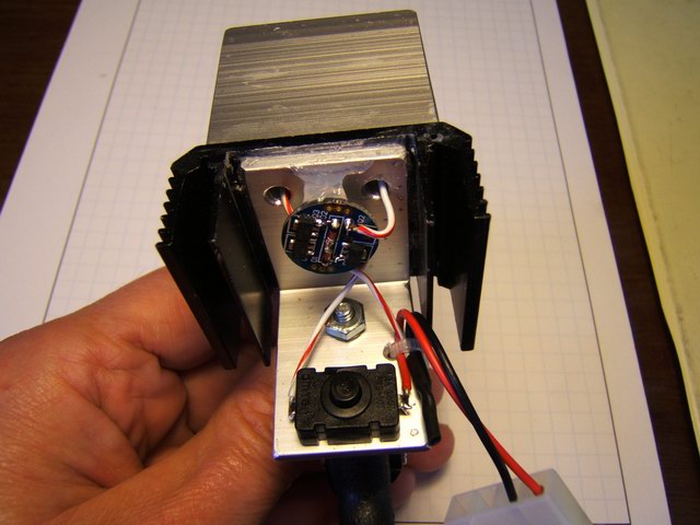
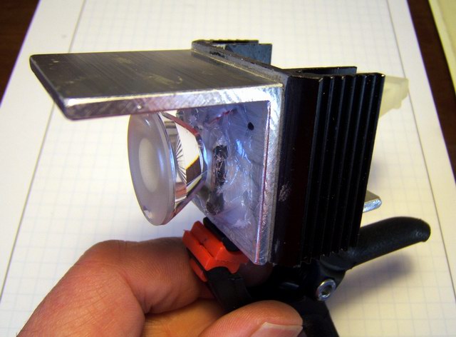
The heat sink is from a surplus TO-3 power transistor bonded to the 1 ½ “ aluminum angle stock. At this point I purchased some Arctic Silver Thermal Adhesive which I used to bond the star LEDs to the heat sink. The thermal conductivity of this epoxy is much greater than the JB Weld, in theory keeping the LED emitter cooler. With the bonding thickness so thin, the temperature drop across the bond is a small part of the heat transfer path. The L2 optics OPTX lens was bonded to the heat sink with GE Silicone II adhesive, in addition to the sticky rubber backing.
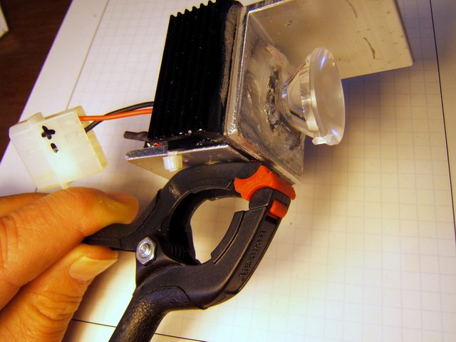
The light uses the same power supplies as prototype 3, either 4 NiMH rechargeable AA batteries, or a 6 volt lantern battery. To make the unit smaller, and since it weighs so little, I used a 2” plastic clamp instead of the 4” clamp in the previous prototypes.