3 Watt LED Bike Light
Experiments
February, 2008,
Rev c
Michael Krabach
Contents
Prototype 2 - Triple Cree with large heat sink
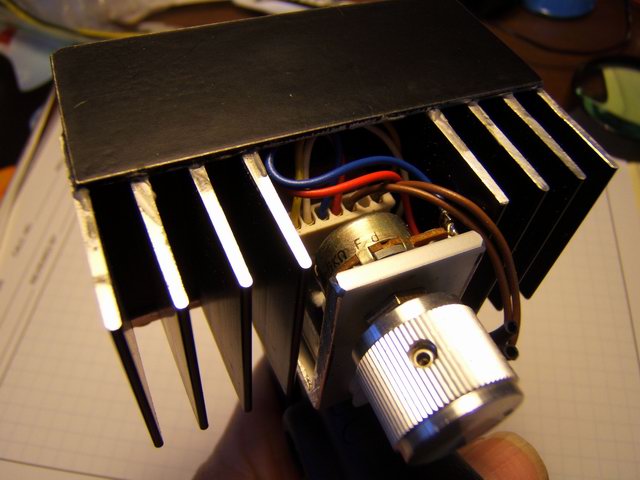
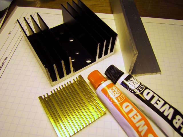
The next experiment was to build a prototype using three Cree 3 watt LEDs. (Note: Currently the Cree and SSC brand LEDs are brighter/watt than the Luxeon brand LEDs, which is why I am using them.) After looking at all the references on the Internet, I had a good idea what was available to build the light and what was being built. Some were very sophisticated, but I wanted to use existing material available in my basement and electronics junk box. One of the primary concerns using 3 watt LEDs is dissipating the heat given off by the LED. (It is a high power diode.) I cut off 1/3 of a large power supply heat sink to give me a base for the LEDs. I cut up a 1 1/2” aluminum angle stock to hold the heat sink and provide a base for the clamp.
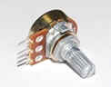
The clamp is the same as Prototype 1. I chose three LEDs in series because the voltage drop across the light would be about the same as Prototype 1 above. A current regulator works more efficiently if the supply voltage is close to the output voltage. With about 11 volts drop across the LEDs in series, I could use a 12 volt lead acid (gel cell) charged to 13 volts or so. I chose a Luxdrive model 3023 Buckpuck 1000 ma current regulator which allows plenty of latitude as long as the supply is a volt or so above the required voltage across the LEDs. These regulators have the capacity to drive three 3 watt LEDs in series. The model I got has output control via a external potentiometer. This allows me to vary the brightness of the light by simply turning the pot. An on/off switch is not really necessary because you can turn the light off with the external pot. The quiescent current drain at this point is less than 500 microamps.
This
light can work with any battery up to 32 volt, which gives the user
the freedom to use Li-ion batteries which would start at a nominal
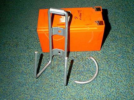
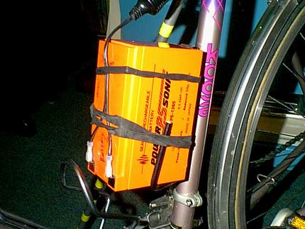
14.2 volts and go up. But in this case I have chose a lead acid (gel
cell) 12 volt battery because they are easy to find, can be recycled
and are relatively cheap. Very good smart chargers are also
available. Li-ion batteries and Li-polymer batteries are dangerous if
not used properly. After reading literature on them and reading
various Internet forums I would only recommend them to someone who
understands the technology and needs a high power to weigh advantage.
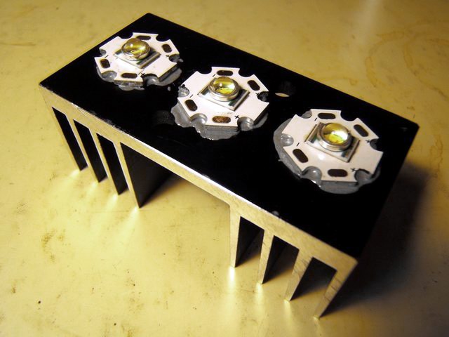
I bonded the LEDs on the heat sink bottom with JB Weld epoxy.
At the time I did not have any Arctic
Silver Thermal Adhesive. After I obtained some, all my LEDs were
bonded to the heat sinks with the Arctic Silver epoxy, but the
bonding of the aluminum stock was still with JB Weld. The Arctic
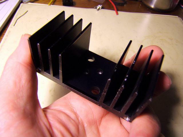
Silver is too expensive for major epoxying. This heat sink already
had a hole in the base to pass the power wires through to the LEDs.
The spacing of the LEDs was determined by diameter of the optics.
Note that the LED emitters are aligned in a horizontal pattern to fit
the optics. This is to allow the diffuser lens to snap on, from top
to bottom. If they are orientated vertically, the diffuser snaps
cannot be accessed in the center LED.
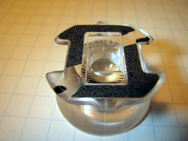
The
Cree LEDs need lens or reflectors to direct the beams. I followed
examples on the Internet and chose plastic lens that can be stuck
over the LEDs. As I built more experiments, I looked for and ordered
other lens and reflectors, but for this light the L2
Optics OPTX with diffuser covers seemed to be the best option.
These are specifically for the Cree XR-E 3 watt LEDs because of the
rectangular emitter base.
A difficulty is installing the lens
over the star backing. The lens come with a sticky rubber tape that
allows you to just stick the lens over the LED dome. (Note:
leave the sticky tape on because the optics seem to be designed to be
used this way. The light beam pattern is degraded slightly if the
sticky tape is removed.)
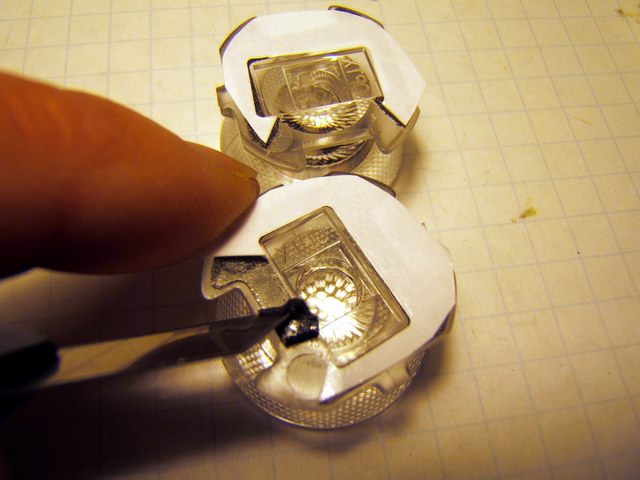
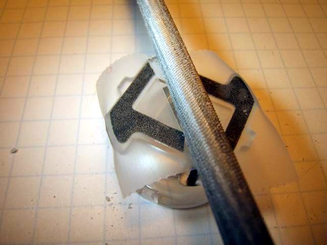
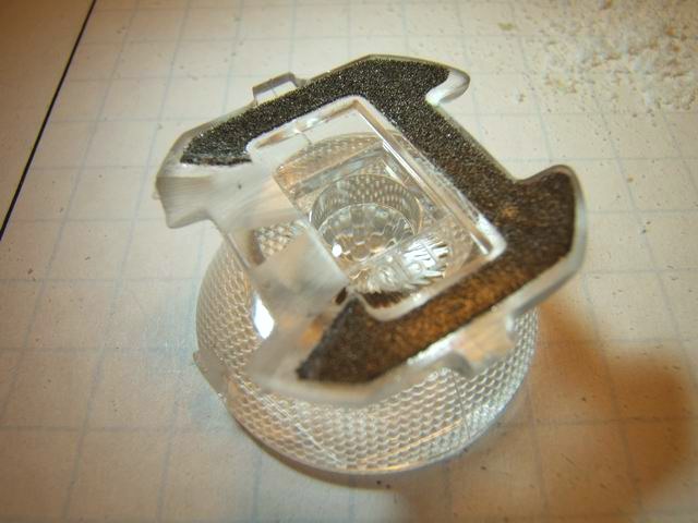
But the soldered wires stand off the star and so channels have to be
filed in the base of the lens to allow clearance for the wires. The
optics come attached to a paper backing which comes off easily. It
has to be removed. A razor was used to cut out the rubber adhesive
where I had to file clearance. Scotch tape was used to mask off the
section of the tape that I did not want to get plastic filings on.
The tape is extremely tenacious and is impossible to clean. A round
(chain saw) file was used to cut notches which can be seen in the
last photo after the tape is removed. To check for clearance, the
excess Scotch tape was cut away and with tape still covering the
sticky part, was set over the LEDs. Filing was continued until a
perfect flat fit was achieved. Then the rest of the Scotch tape was
removed.

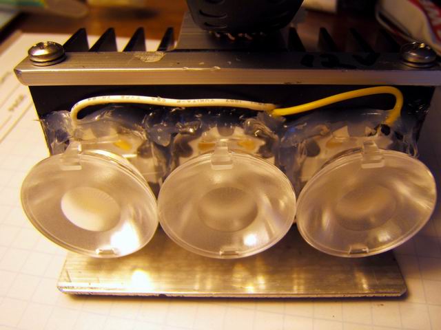
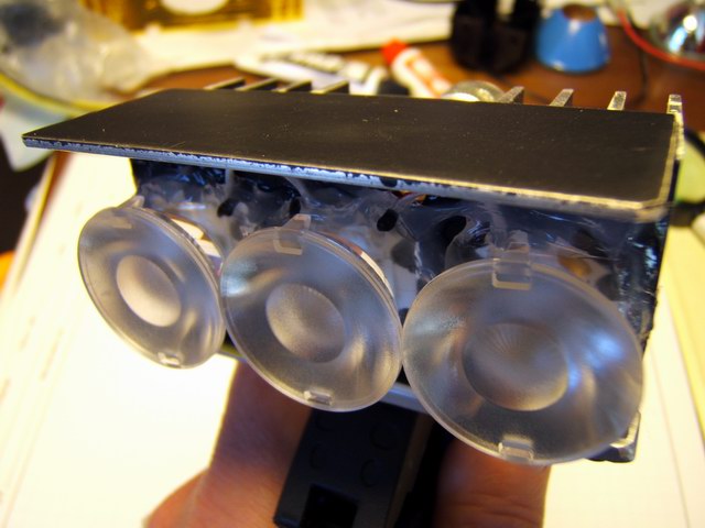
The
optics were stuck to the star LEDs carefully and when aligned pressed
down tightly. GE Silicone II clear adhesive was smeared around the
lens base to waterproof and finalize the attachment of the three
lens. I did not worry about appearance. An advantage of the bare lens
is that when riding, the lights have great visibility from the side.
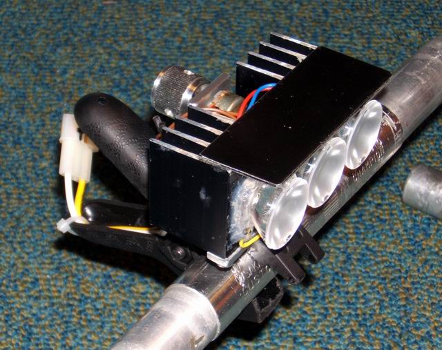
An upper aluminum plate was bonded to the heat sink to prevent glare
in the riders eyes. The L2 Optics have a beam of 6 deg with a very
bright spot in the middle and a larger ring around that. They are
very bright, especially when all three are on. To blend the beam more
evenly I found that optional 8 deg diffusers worked very well. The 16
deg diffusers (also available) were too broad for road riding but
probably would be good for trail riding. The photos below have the 8
deg diffusers clipped on. Note that the clips are in the vertical
orientation which means that the LED emitters must be orientated in
the horizontal position.
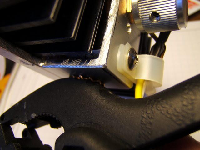
The light was attached to the plastic clamp with a bolt through the bottom of the aluminum angle. An serrated lock washer prevents twisting of the light. The Buckpuck regulator is under the 5K pot in the photo below and wired with a wiring harness. This was inconvenient and the wired Buckpuck model 3023 was used for other prototypes. The 12 volt gel cell is mounted in a water bottle cage on the bike seat tube, or the battery may be carried in panniers. This light turned out to be my favorite light for road riding.